DIY Arduino RC 发射器 遥控器 NRF

在教程中,我们将学习如何构建DIY Arduino RC发射器。我经常需要无线控制我制作的项目,因此我构建了这个多功能无线电控制器,几乎可以用于所有事情。
概述
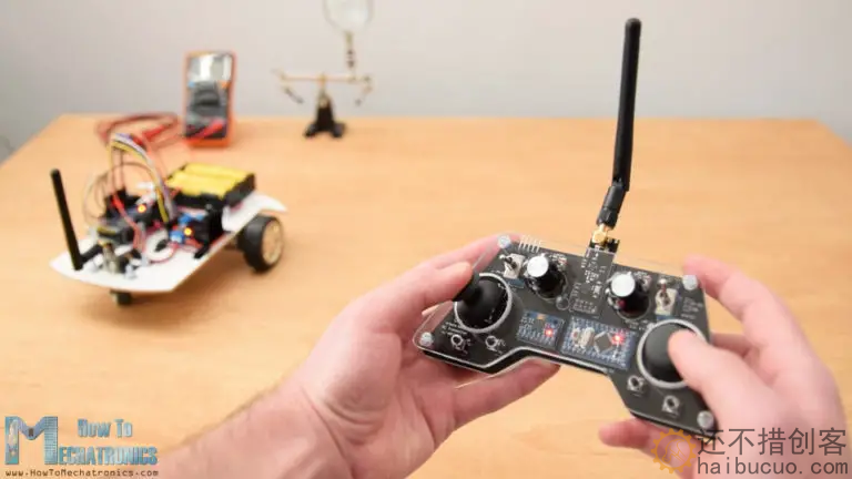
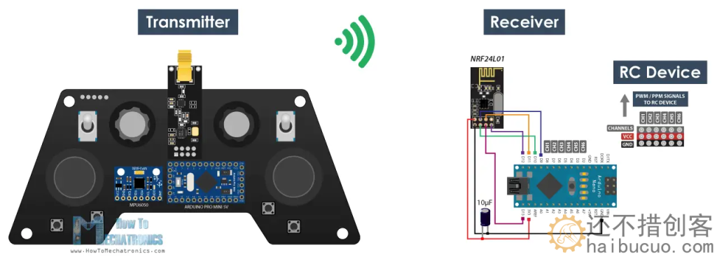
现在,我只需在接收器侧进行一些小的调整,就可以无线控制任何Arduino项目。该发射器也可以用作任何商用RC发射器,用于控制RC玩具,汽车,无人机等。为此,它只需要一个简单的Arduino接收器,然后生成适当的信号来控制这些商业RC设备。
我将通过控制Arduino机器人汽车,控制我之前视频中的Arduino Ant Robot以及使用ESC和一些伺服电机控制无刷直流电机的几个示例来解释本视频中所有工作原理。
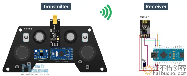
该控制器的无线电通信基于 NRF24L01 收发器模块,如果与放大天线一起使用,它可以在开放空间内具有长达 700 米的稳定范围。它具有 14 个通道,其中 6 个是模拟输入,8 个是数字输入。
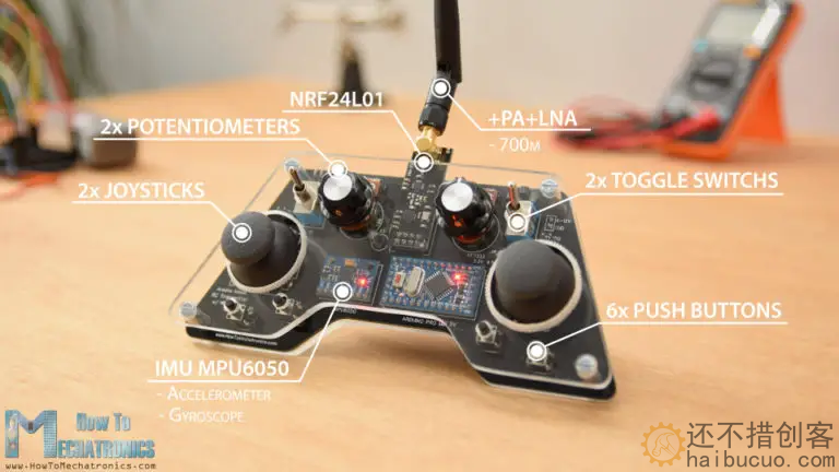
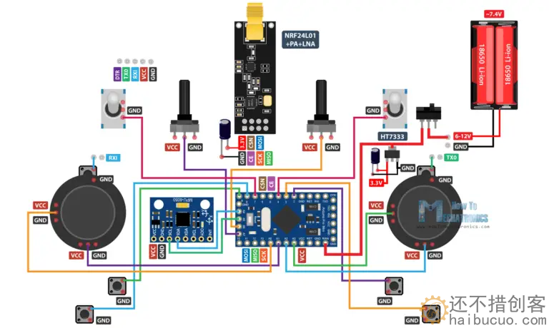
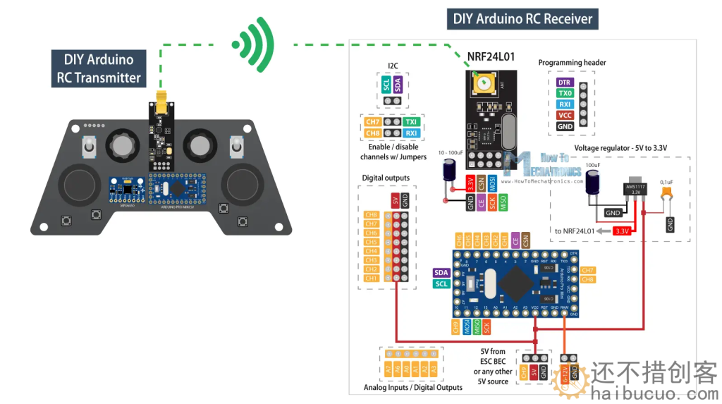
另一方面,NRF24L01模块严格需要3.3V,建议来自专用电源。因此,我们需要使用连接到电池的3.3V稳压器,并将7.4V转换为3.3V。此外,我们需要在模块旁边使用去耦电容器,以保持电压更稳定,因此无线电通信也将更加稳定。NRF24L01模块使用SPI协议与Arduino通信,而MPU6050加速度计和陀螺仪模块使用I2C协议。
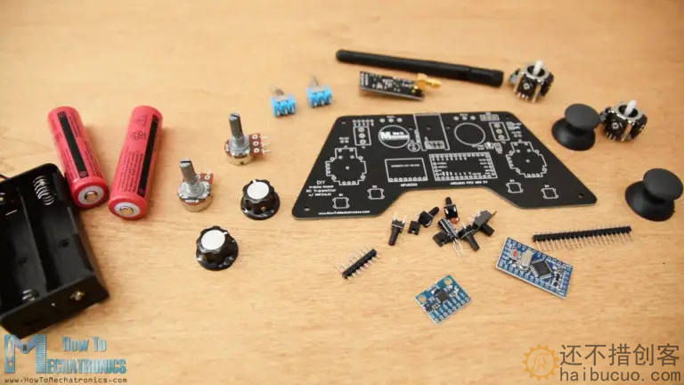
材料清单:
- NRF24L01 Transceiver Module……….. Amazon / Banggood / AliExpress
- NRF24L01 + PA + LNA ……………………. Amazon / Banggood / AliExpress
- Potentiometer ……………………………….. Amazon / Banggood / AliExpress
- Servo Motor …………………………………… Amazon / Banggood / AliExpress
- Toggle Switch …………………………….….. Amazon / Banggood / AliExpress
- Joystick ………………………………………….. Amazon / Banggood / AliExpress – this Joystick comes with a breakout board so you will have to desolder the Joystick from it
- Joystick without breakout board ………… Ebay
- Arduino Pro Mini…………………………….. Amazon / Banggood / AliExpress– You need PCB V2 or V3 version for this boards
- Arduino Pro Mini like the one I used….. Ebay– PCB V1
- HT7333 3.3v voltage regulator ……………. From local electronic shop – PCB V1 & PCB V2
- AMS1117 3.3v voltage regulator …………… Amazon / Banggoood / AliExpress – PCB V3
PCB文件下载:
组装电路板
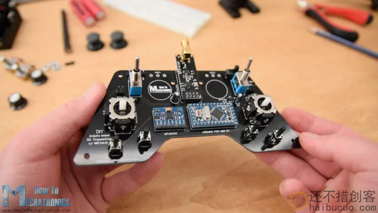
好的,现在我们可以继续组装 PCB.我从焊接Arduino Pro Mini的引脚接头开始。一种简单而好的方法是将它们放在面包板上,这样它们在焊接时就会牢固地保持在原位。
Pro Mini的侧面也有引脚,但请注意,这些引脚位置可能因制造商而异。
对于我拥有的特定型号,每侧需要 5 个引脚,同时将一个 GND 引脚留空,因为我在 PCB 上使用其在 PCB 上的下方区域来运行一些走线。我将Arduino Pro Mini直接焊接到PCB上,并削减了针座的执行长度。紧挨着MPU6050加速度计和陀螺仪模块。
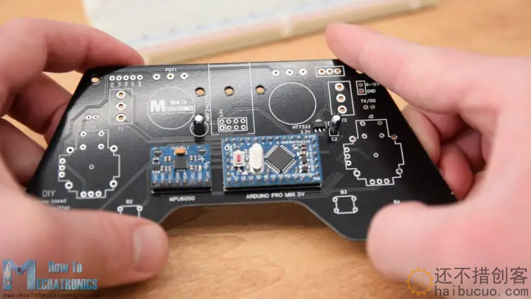
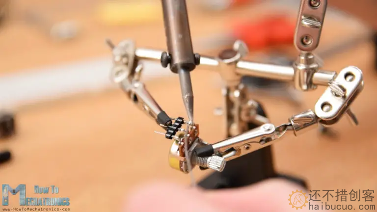
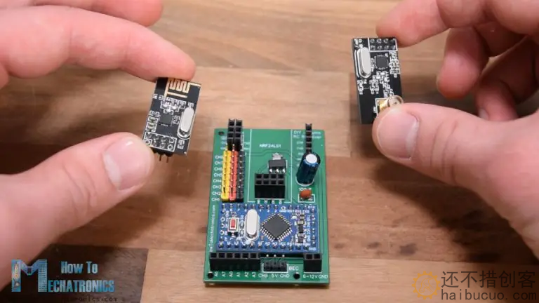
然后,我焊接了3.3V稳压器,旁边有一个电容器,另一个电容器靠近NRF24L01模块。该模块有三个不同的版本,我们可以在这里使用其中任何一个。
接下来,为了将电位计焊接到PCB上,我不得不使用一些引脚接头来扩展它们的引脚
就是这样, 我们的 PCB 现在已经准备好了,所以我们可以继续为它制作盖子.因为我喜欢PCB的外观,并且我希望可见,所以我决定使用透明丙烯酸作为封面。
接下来在背板上,我使用 2 个螺栓连接了电池座。我通过使用四个安装螺栓将背板固定在PCB的背面来完成盖子组装。
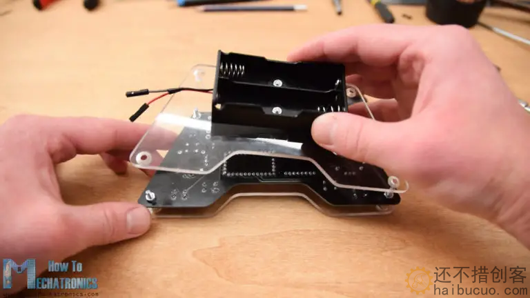
最后,我们可以将电池线连接到电源引脚,插入并固定电位器上的旋钮,插入操纵杆旋钮并将天线连接到NRF24l01模块。就是这样,我们终于完成了DIY Arduino RC发射器。
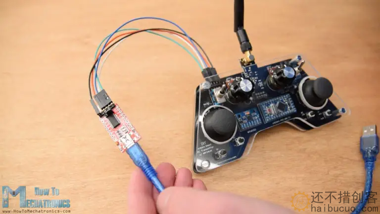
然后在Arduino IDE工具菜单中,我们需要选择Arduino Pro或Pro Mini板,选择处理器的正确版本,选择端口并选择“USBasp”的编程方法。
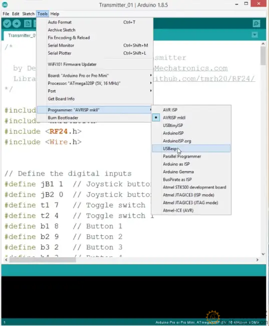
所以现在我们能够将代码上传到Arduino。
基于 DIY Arduino 的 RC 发射器代码
让我们解释一下发射器代码的工作原理。因此,首先我们需要包括用于无线通信的SPI和RF24库,以及用于加速度计模块的I2C库。然后我们需要定义数字输入,下面的程序所需的一些变量,定义无线电对象和通信地址。
*
        DIY Arduino based RC Transmitter
  by Dejan Nedelkovski, www.HowToMechatronics.com
  Library: TMRh20/RF24, https://github.com/tmrh20/RF24/
*/

#include <SPI.h>
#include <nRF24L01.h>
#include <RF24.h>
#include <Wire.h>


// Define the digital inputs
#define jB1 1  // Joystick button 1
#define jB2 0  // Joystick button 2
#define t1 7   // Toggle switch 1
#define t2 4   // Toggle switch 1
#define b1 8   // Button 1
#define b2 9   // Button 2
#define b3 2   // Button 3
#define b4 3   // Button 4

const int MPU = 0x68; // MPU6050 I2C address
float AccX, AccY, AccZ;
float GyroX, GyroY, GyroZ;
float accAngleX, accAngleY, gyroAngleX, gyroAngleY;
float angleX, angleY;
float AccErrorX, AccErrorY, GyroErrorX, GyroErrorY;
float elapsedTime, currentTime, previousTime;
int c = 0;


RF24 radio(5, 6);   // nRF24L01 (CE, CSN)
const byte address[6] = "00001"; // Address

// Max size of this struct is 32 bytes - NRF24L01 buffer limit
struct Data_Package {
  byte j1PotX;
  byte j1PotY;
  byte j1Button;
  byte j2PotX;
  byte j2PotY;
  byte j2Button;
  byte pot1;
  byte pot2;
  byte tSwitch1;
  byte tSwitch2;
  byte button1;
  byte button2;
  byte button3;
  byte button4;
};

Data_Package data; //Create a variable with the above structure

void setup() {
  Serial.begin(9600);

  // Initialize interface to the MPU6050
  initialize_MPU6050();

  // Call this function if you need to get the IMU error values for your module
  //calculate_IMU_error();

  // Define the radio communication
  radio.begin();
  radio.openWritingPipe(address);
  radio.setAutoAck(false);
  radio.setDataRate(RF24_250KBPS);
  radio.setPALevel(RF24_PA_LOW);

  // Activate the Arduino internal pull-up resistors
  pinMode(jB1, INPUT_PULLUP);
  pinMode(jB2, INPUT_PULLUP);
  pinMode(t1, INPUT_PULLUP);
  pinMode(t2, INPUT_PULLUP);
  pinMode(b1, INPUT_PULLUP);
  pinMode(b2, INPUT_PULLUP);
  pinMode(b3, INPUT_PULLUP);
  pinMode(b4, INPUT_PULLUP);

  // Set initial default values
  data.j1PotX = 127; // Values from 0 to 255. When Joystick is in resting position, the value is in the middle, or 127. We actually map the pot value from 0 to 1023 to 0 to 255 because that's one BYTE value
  data.j1PotY = 127;
  data.j2PotX = 127;
  data.j2PotY = 127;
  data.j1Button = 1;
  data.j2Button = 1;
  data.pot1 = 1;
  data.pot2 = 1;
  data.tSwitch1 = 1;
  data.tSwitch2 = 1;
  data.button1 = 1;
  data.button2 = 1;
  data.button3 = 1;
  data.button4 = 1;
}
void loop() {
  // Read all analog inputs and map them to one Byte value
  data.j1PotX = map(analogRead(A1), 0, 1023, 0, 255); // Convert the analog read value from 0 to 1023 into a BYTE value from 0 to 255
  data.j1PotY = map(analogRead(A0), 0, 1023, 0, 255);
  data.j2PotX = map(analogRead(A2), 0, 1023, 0, 255);
  data.j2PotY = map(analogRead(A3), 0, 1023, 0, 255);
  data.pot1 = map(analogRead(A7), 0, 1023, 0, 255);
  data.pot2 = map(analogRead(A6), 0, 1023, 0, 255);
  // Read all digital inputs
  data.j1Button = digitalRead(jB1);
  data.j2Button = digitalRead(jB2);
  data.tSwitch2 = digitalRead(t2);
  data.button1 = digitalRead(b1);
  data.button2 = digitalRead(b2);
  data.button3 = digitalRead(b3);
  data.button4 = digitalRead(b4);
  // If toggle switch 1 is switched on
  if (digitalRead(t1) == 0) {
    read_IMU();    // Use MPU6050 instead of Joystick 1 for controling left, right, forward and backward movements
  }
  // Send the whole data from the structure to the receiver
  radio.write(&data, sizeof(Data_Package));
}

void initialize_MPU6050() {
  Wire.begin();                      // Initialize comunication
  Wire.beginTransmission(MPU);       // Start communication with MPU6050 // MPU=0x68
  Wire.write(0x6B);                  // Talk to the register 6B
  Wire.write(0x00);                  // Make reset - place a 0 into the 6B register
  Wire.endTransmission(true);        //end the transmission
  // Configure Accelerometer
  Wire.beginTransmission(MPU);
  Wire.write(0x1C);                  //Talk to the ACCEL_CONFIG register
  Wire.write(0x10);                  //Set the register bits as 00010000 (+/- 8g full scale range)
  Wire.endTransmission(true);
  // Configure Gyro
  Wire.beginTransmission(MPU);
  Wire.write(0x1B);                   // Talk to the GYRO_CONFIG register (1B hex)
  Wire.write(0x10);                   // Set the register bits as 00010000 (1000dps full scale)
  Wire.endTransmission(true);
}

void calculate_IMU_error() {
  // We can call this funtion in the setup section to calculate the accelerometer and gury data error. From here we will get the error values used in the above equations printed on the Serial Monitor.
  // Note that we should place the IMU flat in order to get the proper values, so that we then can the correct values
  // Read accelerometer values 200 times
  while (c < 200) {
    Wire.beginTransmission(MPU);
    Wire.write(0x3B);
    Wire.endTransmission(false);
    Wire.requestFrom(MPU, 6, true);
    AccX = (Wire.read() << 8 | Wire.read()) / 4096.0 ;
    AccY = (Wire.read() << 8 | Wire.read()) / 4096.0 ;
    AccZ = (Wire.read() << 8 | Wire.read()) / 4096.0 ;
    // Sum all readings
    AccErrorX = AccErrorX + ((atan((AccY) / sqrt(pow((AccX), 2) + pow((AccZ), 2))) * 180 / PI));
    AccErrorY = AccErrorY + ((atan(-1 * (AccX) / sqrt(pow((AccY), 2) + pow((AccZ), 2))) * 180 / PI));
    c++;
  }
  //Divide the sum by 200 to get the error value
  AccErrorX = AccErrorX / 200;
  AccErrorY = AccErrorY / 200;
  c = 0;
  // Read gyro values 200 times
  while (c < 200) {
    Wire.beginTransmission(MPU);
    Wire.write(0x43);
    Wire.endTransmission(false);
    Wire.requestFrom(MPU, 4, true);
    GyroX = Wire.read() << 8 | Wire.read();
    GyroY = Wire.read() << 8 | Wire.read();
    // Sum all readings
    GyroErrorX = GyroErrorX + (GyroX / 32.8);
    GyroErrorY = GyroErrorY + (GyroY / 32.8);
    c++;
  }
  //Divide the sum by 200 to get the error value
  GyroErrorX = GyroErrorX / 200;
  GyroErrorY = GyroErrorY / 200;
  // Print the error values on the Serial Monitor
  Serial.print("AccErrorX: ");
  Serial.println(AccErrorX);
  Serial.print("AccErrorY: ");
  Serial.println(AccErrorY);
  Serial.print("GyroErrorX: ");
  Serial.println(GyroErrorX);
  Serial.print("GyroErrorY: ");
  Serial.println(GyroErrorY);
}

void read_IMU() {
  // === Read acceleromter data === //
  Wire.beginTransmission(MPU);
  Wire.write(0x3B); // Start with register 0x3B (ACCEL_XOUT_H)
  Wire.endTransmission(false);
  Wire.requestFrom(MPU, 6, true); // Read 6 registers total, each axis value is stored in 2 registers
  //For a range of +-8g, we need to divide the raw values by 4096, according to the datasheet
  AccX = (Wire.read() << 8 | Wire.read()) / 4096.0; // X-axis value
  AccY = (Wire.read() << 8 | Wire.read()) / 4096.0; // Y-axis value
  AccZ = (Wire.read() << 8 | Wire.read()) / 4096.0; // Z-axis value

  // Calculating angle values using
  accAngleX = (atan(AccY / sqrt(pow(AccX, 2) + pow(AccZ, 2))) * 180 / PI) + 1.15; // AccErrorX ~(-1.15) See the calculate_IMU_error()custom function for more details
  accAngleY = (atan(-1 * AccX / sqrt(pow(AccY, 2) + pow(AccZ, 2))) * 180 / PI) - 0.52; // AccErrorX ~(0.5)

  // === Read gyro data === //
  previousTime = currentTime;        // Previous time is stored before the actual time read
  currentTime = millis();            // Current time actual time read
  elapsedTime = (currentTime - previousTime) / 1000;   // Divide by 1000 to get seconds
  Wire.beginTransmission(MPU);
  Wire.write(0x43); // Gyro data first register address 0x43
  Wire.endTransmission(false);
  Wire.requestFrom(MPU, 4, true); // Read 4 registers total, each axis value is stored in 2 registers
  GyroX = (Wire.read() << 8 | Wire.read()) / 32.8; // For a 1000dps range we have to divide first the raw value by 32.8, according to the datasheet
  GyroY = (Wire.read() << 8 | Wire.read()) / 32.8;
  GyroX = GyroX + 1.85; //// GyroErrorX ~(-1.85)
  GyroY = GyroY - 0.15; // GyroErrorY ~(0.15)
  // Currently the raw values are in degrees per seconds, deg/s, so we need to multiply by sendonds (s) to get the angle in degrees
  gyroAngleX = GyroX * elapsedTime;
  gyroAngleY = GyroY * elapsedTime;

  // Complementary filter - combine acceleromter and gyro angle values
  angleX = 0.98 * (angleX + gyroAngleX) + 0.02 * accAngleX;
  angleY = 0.98 * (angleY + gyroAngleY) + 0.02 * accAngleY;
  // Map the angle values from -90deg to +90 deg into values from 0 to 255, like the values we are getting from the Joystick
  data.j1PotX = map(angleX, -90, +90, 255, 0);
  data.j1PotY = map(angleY, -90, +90, 0, 255);
}
接收器调试代码
现在让我们来看看如何接收这些数据。下面是一个简单的 Arduino 和 NRF24L01 接收器原理图。当然,您可以使用任何其他Arduino板。
/*
    DIY Arduino based RC Transmitter Project
              == Receiver Code ==

  by Dejan Nedelkovski, www.HowToMechatronics.com
  Library: TMRh20/RF24, https://github.com/tmrh20/RF24/
*/
#include <SPI.h>
#include <nRF24L01.h>
#include <RF24.h>
RF24 radio(10, 9);   // nRF24L01 (CE, CSN)
const byte address[6] = "00001";

unsigned long lastReceiveTime = 0;
unsigned long currentTime = 0;

// Max size of this struct is 32 bytes - NRF24L01 buffer limit
struct Data_Package {
  byte j1PotX;
  byte j1PotY;
  byte j1Button;
  byte j2PotX;
  byte j2PotY;
  byte j2Button;
  byte pot1;
  byte pot2;
  byte tSwitch1;
  byte tSwitch2;
  byte button1;
  byte button2;
  byte button3;
  byte button4;
};

Data_Package data; //Create a variable with the above structure

void setup() {
  Serial.begin(9600);
  radio.begin();
  radio.openReadingPipe(0, address);
  radio.setAutoAck(false);
  radio.setDataRate(RF24_250KBPS);
  radio.setPALevel(RF24_PA_LOW);
  radio.startListening(); //  Set the module as receiver
  resetData();
}
void loop() {
  // Check whether there is data to be received
  if (radio.available()) {
    radio.read(&data, sizeof(Data_Package)); // Read the whole data and store it into the 'data' structure
    lastReceiveTime = millis(); // At this moment we have received the data
  }
  // Check whether we keep receving data, or we have a connection between the two modules
  currentTime = millis();
  if ( currentTime - lastReceiveTime > 1000 ) { // If current time is more then 1 second since we have recived the last data, that means we have lost connection
    resetData(); // If connection is lost, reset the data. It prevents unwanted behavior, for example if a drone has a throttle up and we lose connection, it can keep flying unless we reset the values
  }
  // Print the data in the Serial Monitor
  Serial.print("j1PotX: ");
  Serial.print(data.j1PotX);
  Serial.print("; j1PotY: ");
  Serial.print(data.j1PotY);
  Serial.print("; button1: ");
  Serial.print(data.button1);
  Serial.print("; j2PotX: ");
  Serial.println(data.j2PotX);
}

void resetData() {
  // Reset the values when there is no radio connection - Set initial default values
  data.j1PotX = 127;
  data.j1PotY = 127;
  data.j2PotX = 127;
  data.j2PotY = 127;
  data.j1Button = 1;
  data.j2Button = 1;
  data.pot1 = 1;
  data.pot2 = 1;
  data.tSwitch1 = 1;
  data.tSwitch2 = 1;
  data.button1 = 1;
  data.button2 = 1;
  data.button3 = 1;
  data.button4 = 1;
}
3。案例
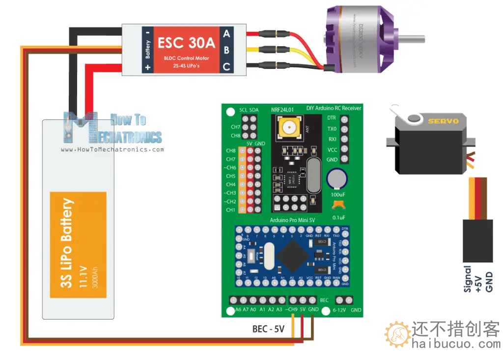
3.1六通道代码
/*
DIY Arduino based RC Transmitter Project
== Receiver Code - ESC and Servo Control ==
by Dejan Nedelkovski, www.HowToMechatronics.com
Library: TMRh20/RF24, https://github.com/tmrh20/RF24/
*/
#include <SPI.h>
#include <nRF24L01.h>
#include <RF24.h>
#include <Servo.h>
RF24 radio(10, 9); // nRF24L01 (CE, CSN)
const byte address[6] = "00001";
unsigned long lastReceiveTime = 0;
unsigned long currentTime = 0;
Servo esc; // create servo object to control the ESC
Servo servo1;
Servo servo2;
int escValue, servo1Value, servo2Value;
// Max size of this struct is 32 bytes - NRF24L01 buffer limit
struct Data_Package {
byte j1PotX;
byte j1PotY;
byte j1Button;
byte j2PotX;
byte j2PotY;
byte j2Button;
byte pot1;
byte pot2;
byte tSwitch1;
byte tSwitch2;
byte button1;
byte button2;
byte button3;
byte button4;
};
Data_Package data; //Create a variable with the above structure
void setup() {
Serial.begin(9600);
radio.begin();
radio.openReadingPipe(0, address);
radio.setAutoAck(false);
radio.setDataRate(RF24_250KBPS);
radio.setPALevel(RF24_PA_LOW);
radio.startListening(); // Set the module as receiver
resetData();
esc.attach(9);
servo1.attach(3);
servo2.attach(4);
}
void loop() {
// Check whether we keep receving data, or we have a connection between the two modules
currentTime = millis();
if ( currentTime - lastReceiveTime > 1000 ) { // If current time is more then 1 second since we have recived the last data, that means we have lost connection
resetData(); // If connection is lost, reset the data. It prevents unwanted behavior, for example if a drone jas a throttle up, if we lose connection it can keep flying away if we dont reset the function
}
// Check whether there is data to be received
if (radio.available()) {
radio.read(&data, sizeof(Data_Package)); // Read the whole data and store it into the 'data' structure
lastReceiveTime = millis(); // At this moment we have received the data
}
// Controlling servos
servo1Value = map(data.j2PotX, 0, 255, 0, 180);
servo2Value = map(data.j2PotY, 0, 255, 0, 180);
servo1.write(servo1Value);
servo2.write(servo2Value);
// Controlling brushless motor with ESC
escValue = map(data.pot1, 0, 255, 1000, 2000); // Map the receiving value form 0 to 255 to 0 1000 to 2000, values used for controlling ESCs
esc.writeMicroseconds(escValue); // Send the PWM control singal to the ESC
}
void resetData() {
// Reset the values when there is no radio connection - Set initial default values
data.j1PotX = 127;
data.j1PotY = 127;
data.j2PotX = 127;
data.j2PotY = 127;
data.j1Button = 1;
data.j2Button = 1;
data.pot1 = 1;
data.pot2 = 1;
data.tSwitch1 = 1;
data.tSwitch2 = 1;
data.button1 = 1;
data.button2 = 1;
data.button3 = 1;
data.button4 = 1;
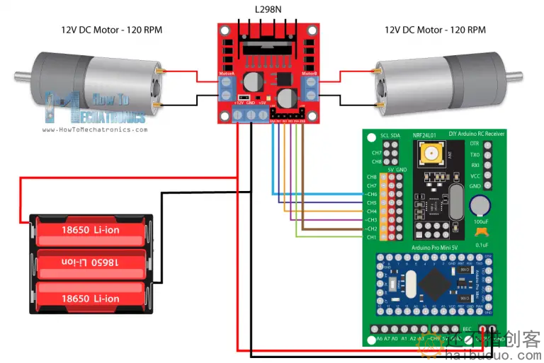
}遥控车L298N代码
/*
   Arduino RC Receiver - Car Example
   by Dejan, www.HowToMechatronics.com
   Library: TMRh20/RF24, https://github.com/tmrh20/RF24/
*/
#include <SPI.h>
#include <nRF24L01.h>
#include <RF24.h>

#define enA 9  // Arduino pin D9 - CH6 on PCB board - PWM output
#define in1 8  // D8 - CH5
#define in2 7  // D7 - CH4
#define in3 6  // D6 - CH3
#define in4 4  // D4 - CH1
#define enB 5  // D5 - CH2 - PWM output

RF24 radio(3, 2);   // nRF24L01 (CE, CSN)
const byte address[6] = "00001";
unsigned long lastReceiveTime = 0;
unsigned long currentTime = 0;

// Max size of this struct is 32 bytes
struct Data_Package {
  byte j1PotX;
  byte j1PotY;
  byte j1Button;
  byte j2PotX;
  byte j2PotY;
  byte j2Button;
  byte pot1;
  byte pot2;
  byte tSwitch1;
  byte tSwitch2;
  byte button1;
  byte button2;
  byte button3;
  byte button4;
};

Data_Package data; //Create a variable with the above structure

int  steering, throttle;
int motorSpeedA = 0;
int motorSpeedB = 0;

void setup() {
  pinMode(enA, OUTPUT);
  pinMode(enB, OUTPUT);
  pinMode(in1, OUTPUT);
  pinMode(in2, OUTPUT);
  pinMode(in3, OUTPUT);
  pinMode(in4, OUTPUT);
  //Serial.begin(9600);
  radio.begin();
  radio.openReadingPipe(0, address);
  radio.setAutoAck(false);
  radio.setDataRate(RF24_250KBPS);
  radio.setPALevel(RF24_PA_LOW);
  radio.startListening(); //  Set the module as receiver
  resetData();
}
void loop() {
  // Check whether we keep receving data, or we have a connection between the two modules
  currentTime = millis();
  if ( currentTime - lastReceiveTime > 1000 ) { // If current time is more then 1 second since we have recived the last data, that means we have lost connection
    resetData(); // If connection is lost, reset the data. It prevents unwanted behavior, for example if a drone jas a throttle up, if we lose connection it can keep flying away if we dont reset the function
  }
  // Check whether there is data to be received
  if (radio.available()) {
    radio.read(&data, sizeof(Data_Package)); // Read the whole data and store it into the 'data' structure
    lastReceiveTime = millis(); // At this moment we have received the data
  }

  // Parse the data from the Joystic 1 to the throttle and steering variables
  throttle = data.j1PotY;
  steering = data.j1PotX;

  // Throttle used for forward and backward control
  // Joystick values: 0 to 255; down = 0; middle = 127; up = 255
  if (throttle < 110) {
    // Set Motor A backward
    digitalWrite(in1, HIGH);
    digitalWrite(in2, LOW);
    // Set Motor B backward
    digitalWrite(in3, HIGH);
    digitalWrite(in4, LOW);
    // Convert the declining throttle readings for going backward from 110 to 0 into 0 to 255 value for the PWM signal for increasing the motor speed
    motorSpeedA = map(throttle, 110, 0, 0, 255);
    motorSpeedB = map(throttle, 110, 0, 0, 255);
  }
  else if (throttle > 140) {
    // Set Motor A forward
    digitalWrite(in1, LOW);
    digitalWrite(in2, HIGH);
    // Set Motor B forward
    digitalWrite(in3, LOW);
    digitalWrite(in4, HIGH);
    // Convert the increasing throttle readings for going forward from 140 to 255 into 0 to 255 value for the PWM signal for increasing the motor speed
    motorSpeedA = map(throttle, 140, 255, 0, 255);
    motorSpeedB = map(throttle, 140, 255, 0, 255);
  }
  // If joystick stays in middle the motors are not moving
  else {
    motorSpeedA = 0;
    motorSpeedB = 0;
  }
  // Steering used for left and right control
  if (steering < 110) {
    // Convert the declining steering readings from 140 to 255 into increasing 0 to 255 value
    int xMapped = map(steering, 110, 0, 0, 255);
    // Move to left - decrease left motor speed, increase right motor speed
    motorSpeedA = motorSpeedA - xMapped;
    motorSpeedB = motorSpeedB + xMapped;
    // Confine the range from 0 to 255
    if (motorSpeedA < 0) {
      motorSpeedA = 0;
    }
    if (motorSpeedB > 255) {
      motorSpeedB = 255;
    }
  }
  if (steering > 140) {
    // Convert the increasing steering readings from 110 to 0 into 0 to 255 value
    int xMapped = map(steering, 140, 255, 0, 255);
    // Move right - decrease right motor speed, increase left motor speed
    motorSpeedA = motorSpeedA + xMapped;
    motorSpeedB = motorSpeedB - xMapped;
    // Confine the range from 0 to 255
    if (motorSpeedA > 255) {
      motorSpeedA = 255;
    }
    if (motorSpeedB < 0) {
      motorSpeedB = 0;
    }
  }
  // Prevent buzzing at low speeds (Adjust according to your motors. My motors couldn't start moving if PWM value was below value of 70)
  if (motorSpeedA < 70) {
    motorSpeedA = 0;
  }
  if (motorSpeedB < 70) {
    motorSpeedB = 0;
  }
  analogWrite(enA, motorSpeedA); // Send PWM signal to motor A
  analogWrite(enB, motorSpeedB); // Send PWM signal to motor B
}
void resetData() {
  // Reset the values when there is no radio connection - Set initial default values
  data.j1PotX = 127;
  data.j1PotY = 127;
  data.j2PotX = 127;
  data.j2PotY = 127;
  data.j1Button = 1;
  data.j2Button = 1;
  data.pot1 = 1;
  data.pot2 = 1;
  data.tSwitch1 = 1;
  data.tSwitch2 = 1;
  data.button1 = 1;
  data.button2 = 1;
  data.button3 = 1;
  data.button4 = 1;
}
无刷电机代码
原文
DIY Arduino RC 发射器 – 如何机电一体化 (howtomechatronics.com)
/*
  DIY RC Receiver - Servos and Brushless motors control
  by Dejan, www.HowToMechatronics.com
  Library: TMRh20/RF24, https://github.com/tmrh20/RF24/
*/
#include <SPI.h>
#include <nRF24L01.h>
#include <RF24.h>
#include <Servo.h>

RF24 radio(3, 2);   // nRF24L01 (CE, CSN)
const byte address[6] = "00001";
unsigned long lastReceiveTime = 0;
unsigned long currentTime = 0;
Servo esc;  // create servo object to control the ESC
Servo servo1;
Servo servo2;
int escValue, servo1Value, servo2Value;
// Max size of this struct is 32 bytes - NRF24L01 buffer limit
struct Data_Package {
  byte j1PotX;
  byte j1PotY;
  byte j1Button;
  byte j2PotX;
  byte j2PotY;
  byte j2Button;
  byte pot1;
  byte pot2;
  byte tSwitch1;
  byte tSwitch2;
  byte button1;
  byte button2;
  byte button3;
  byte button4;
};
Data_Package data; //Create a variable with the above structure
void setup() {
  Serial.begin(9600);
  radio.begin();
  radio.openReadingPipe(0, address);
  radio.setAutoAck(false);
  radio.setDataRate(RF24_250KBPS);
  radio.setPALevel(RF24_PA_LOW);
  radio.startListening(); //  Set the module as receiver
  resetData();
  esc.attach(10);   // Arduino digital pin D10 - CH9 on PCB board
  servo1.attach(4); // D4 - CH1
  servo2.attach(5); // D5 - CH2
}
void loop() {

  // Check whether we keep receving data, or we have a connection between the two modules
  currentTime = millis();
  if ( currentTime - lastReceiveTime > 1000 ) { // If current time is more then 1 second since we have recived the last data, that means we have lost connection
    resetData(); // If connection is lost, reset the data. It prevents unwanted behavior, for example if a drone jas a throttle up, if we lose connection it can keep flying away if we dont reset the function
  }

  // Check whether there is data to be received
  if (radio.available()) {
    radio.read(&data, sizeof(Data_Package)); // Read the whole data and store it into the 'data' structure
    lastReceiveTime = millis(); // At this moment we have received the data
  }

  // Controlling servos
  servo1Value = map(data.j2PotX, 0, 255, 0, 180); // Map the receiving value form 0 to 255 to 0 to 180(degrees), values used for controlling servos
  servo2Value = map(data.j2PotY, 0, 255, 0, 180);
  servo1.write(servo1Value);
  servo2.write(servo2Value);

  // Controlling brushless motor with ESC
  escValue = map(data.j1PotY, 127, 255, 1000, 2000); // Map the receiving value form 127 to 255 to  1000 to 2000, values used for controlling ESCs
  esc.writeMicroseconds(escValue); // Send the PWM control singal to the ESC

}
void resetData() {
  // Reset the values when there is no radio connection - Set initial default values
  data.j1PotX = 127;
  data.j1PotY = 127;
  data.j2PotX = 127;
  data.j2PotY = 127;
  data.j1Button = 1;
  data.j2Button = 1;
  data.pot1 = 1;
  data.pot2 = 1;
  data.tSwitch1 = 1;
  data.tSwitch2 = 1;
  data.button1 = 1;
  data.button2 = 1;
  data.button3 = 1;
  data.button4 = 1;
}
更新:
2023.08.22
2023年8月7日 创建


评论列表(1条)
https://howtomechatronics.com/projects/diy-arduino-rc-receiver/